Regarding
Circuit Boards for the
Hybrid Cascode General Purpose AGC IF Amplifier
w7zoi & wa7mlh, QST, December, 2007 pp 30-33.
(11Nov to 12Dec07, 2Jan08,
7April13, 26may13)
Click here for errata. (latest 3Dec07)
Click here for applications
information (Modifications, S-Meter, Crystal Filters, Output Attenuation)
(2Jan08)
Click here to see a discussion of some
stability issues. (2Dec07)
Go to the bottom of this page to
see info regarding the layouts. (26may13)
Roger, KA7EXM, has closed his
on-line store and no longer has boards or kitlets. Board
photos are shown below for those still building. We made a few minor
modifications to the design over that in QST to help the builder.
You can see these in the applications page
and the errata page. A schematic is shown below.
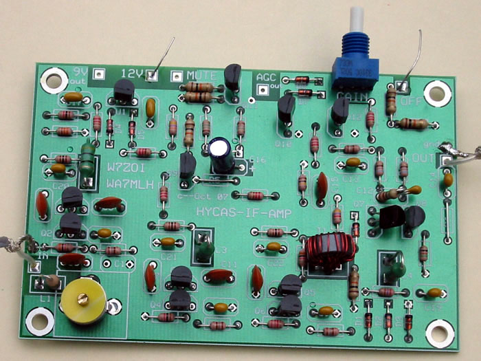
One of the boards loaded with components. This was a "test"
version of the project. The resistors used in the board are 1/8 Watt
with a size much smaller than 1/4 Watt. None of the parts are stressed.
(The two resistors in the upper right corner are traditional 1/4 W
so you can compare.) The pot is mounted on the board. The
board layout accommodates this, but the pot will eventually be mounted on
a receiver front panel. Two resistors are replaced with wire
jumpers; this was intended. The pads are there to allow flexibility
for the experimenter. No stability problems were noted with this board.
The problem of overall
stability is considered by clicking here. There is nothing critical
about the transformer. Since it is wound on a high permeability core,
about any winding style is fine. The differential pair, Q7
and Q8, are on the right side of the board about half way up from the bottom.
The modification "TeePee" is seen just above the pair. See the
errata for details. Anyone wanting the layout should write me.
This is the left side of the schematic diagram, as built for one of the
parts kits.
And this is the right hand side of the schematic. There are minor
differences from the QST schematic.
Click here to see errata for the December
2007 QST article.
PCB Layouts
(26may13)
Although there are no longer commercially built boards, some folks are willing
to make their own boards. As a service, we are making our layouts available.
Our boards were built via ExpressPCB. This service is available
on line from ExpressPCB.com. Going to that site will allow a
reader to download their layout program. I find the program very easy
to use. Once the program has been downloaded, it can be used to view
the two files, which are in the zip file below. Note that there
are some board updates that have been done to enhance stability, etc.
These are not in all of the boards.
These layouts are offered as a service to those wishing to build their own
boards and then to build a version of the IF amplifier. But this
is a HOMEBREW project for the reader. We take no responsibility
for accuracy -- you are on your own.
To download the layouts, just click here and save the zip
file to your computer. The zip file includes a text file relating
to the SMT layout, two layout files, and some figures that might be useful.