Tracking Generator Modifications (31August06, 5Jan07, Major Update 2April2010 )
w7zoi, April,
2010
Bob Kopski, K3NHI, and John
Lawson, K5IRK, have come up with a Simple Tracking
Generator (STG) to go with the QST Spectrum Analyzer that K7TAU
and I presented in the August/September 1998 issue of QST. Our
original tracking generator circuit appeared in the November, 1999 QST.
We used a high level mixer for that design. In retrospect,
that was not really required. We had generated a power of +6 dBm,
but then attenuated it through a pad to reach the desired output level of
0 dBm. A normal diode ring mixer would have done as well.
Our original design used a crystal controlled 5th overtone oscillator.
Although ideal, crystal control is not mandatory for the wide analyzer
bandwidths available in our analyzer. A more detailed block diagram
is shown below.
Bob and John did several
things to simplify the overall design. First, they eliminated crystal
control in the 110 MHz oscillator. Instead, an LC circuit was used.
Their mixer was the popular NE602 (or 612) and they employed the
built-in oscillator on the chip. A trimmer capacitor sets the frequency.
A varactor diode is controlled by a front panel pot for exact adjustment.
This is necessary, for there will be some thermal drift, although
it is not severe. It is useful to use a high quality trimmer capacitor
in the circuit. Bob used a home made one in his version of
the TG while John used a commercially available part. Multiple
turns for the adjustment are worthwhile.
The mixer in this analyzer
is the Gilbert-Cell integral to the NE602. This mixer works with
lower levels than are normally used with diode rings, so the signal levels
throughout the system are smaller. The signal that is extracted
from the SA must be attenuated before it can be used as an input to the
Gilbert Cell. The output from the NE602 is applied directly to an
amplifier with a very low input impedance. This operates like the
upper transistor in a cascode connection, eliminating the attenuation characteristics
of the normal NE602 output capacitance, serving to extend bandwidth.
The post mixer amplifier
has a 50 Ohm output impedance that serves well to drive the low pass filter
that eliminates the image component. The SMT low pass shown
below in this note is recommended. If commercial SMT inductors cannot
be found, a designer/builder could wind inductors in the threads of a machine
screw. A coil winding program to facilitate this is found in the
"experiments and designs" section of this web site. The home coils
should be small and spaced at least a coil diameter or length from each other.
They should be measured before insertion in the circuit.
The amplifier topology that
Bob and John used in the STG consists of a common base stage with a cascade
follower. This circuit is quite robust with excellent bandwidth.
The low pass filter drives
a two stage amplifier with a 50 Ohm input impedance. This provides
enough gain to generate an output close to 0 dBm. An exact output
power value is not really needed. The detailed schematic for
the STG is shown below:
Although this tracking
generator is much simpler than the original, it can still be a challenging
project. The tracking generator is much like the transmitter portion
of a familiar amateur radio transceiver. When the "receiver" portion
of the system tunes, or sweeps to a new frequency, the transmitter tracks
right along with it. However, there is one major difference, one that
explains the potential difficulty in the measurement project. Unlike
the usual communications transceiver, the two parts of a SA/TG pair must
both operate at full performance at the same time!
Good shielding is mandatory, as is effective bypassing
and decoupling. One of the things discovered by Ed, KG4ARN
(see info below) was that high quality feed through capacitors are worthwhile.
The unit that he suggested is a Spectrum Control model 1201-066.
This "bolt in the wall" pi filter is more than a mere capacitor
and has a specified attenuation of 68 dB at 100 MHz. The inexpensive
parts, like some "good buys" that I got on eBay, are only specified for
45 dB or so. Ed had measured some of the caps he was using
as only offering 30 dB attenuation at 100 MHz. The good parts mentioned
are available from Mouser for about $6 each. It may be necessary
to use these parts in a couple of the VHF parts of the SA as well as in the
supply line powering the tracking generator board. A tightly
shielded box is mandatory for the TG. Good shielding is equally important
for the sections of the spectrum analyzer.
Much more information on
the new TG is provided by Bob and John on the EMRFD Yahoo Group in the "files"
section as "K3NHI_K5IRK_STG". Bob's analyzer is one that tunes
from DC to 100 MHz with a first IF near 150 MHz. John's is more of
a carbon copy of the QST design. John found no measurable difference
between his STG and the original TG design. But high quality feedthrough
capacitors are important in both. Many
thanks to both Bob and John for their efforts to generate a great new design.
applies to the original tracking generator.
Comments that apply to the STG are in red.
An email in 2006 from Ed
Milcarsky, KG4ARN, dealt with a couple of problems with the tracking generator.
First, he was seeing a "baseline rise" when the tracking
generator was powered, but disconnected. Baseline
rise is a phenomenon where the normal noise floor at the bottom of the
of the screen increases uniformly across the screen. This degrades
the minimum signal that can be detected, which then compromises the dynamic
range that can be achieved with the spectrum analyzer -- tracking generator
combination. Baseline rise usually occurs when a non-swept
signal at the analyzer IF gets into the IF and eventually to the log detector.
In this case, the Baseline rise would come from energy at
10 MHz (unlikely) or at 110 (most probable) MHz. The other problem
that Ed saw was excess energy at high frequency (above 70 MHz) coming
from the tracking generator output. Ed didn't say how he measured
this. He speculated that there may have been problems related
to a poor high frequency termination. To fix this, Ed modified
the block diagram of the tracking generator.
The figure below shows the changes that Ed made. The top part
of the figure (A) shows the original block diagram while the diagram
below that in (B) shows the modification that Ed did. He moved
the 6 dB pad to directly follow the mixer. This will then
guarantee a reasonable termination for all high and low frequency mixer
products. The pad is followed by the low pass filter. Ed
elected to use a Mini-Circuits PLP-70 filter in this slot. (Hey,
why not. Everything else in the TG is from Mini-Circuits.)
These details are not nearly as important
with Kopski and Lawson's STG, for the Gilbert Cell mixer is not prone to
the problems with termination sensitivity and signal reflection that we
enjoy with diode rings.
The note I got from Ed indicated that he pulled the output directly
from U3 with no pad at the output. This is probably fine for
most applications. The available output power should be around
0 dBm. For critical applications where it is important to
have a very clean output impedance, it might be useful to include a 10
dB pad (100 Ohm parallel resistors with 68 Ohms series) in the output as
I have shown the part B of the figure above. This is up to
the experimenter/builder. The amplifiers
used in the STG have well defined impedances at both input and output,
without the interactions that are found in amplifiers with heavy parallel
feedback.
Ed still had some anomalous behavior after the changes to the block diagram. He finally solved the last baseline rise and related problems by placing the 110 MHz LO in a separate box with high quality feedthrough capacitors. John Lawson had a similar experience.
Part C of the figure shows
a SMT filter that should be suitable for the output of the tracking generator
or for the front end of the analyzer itself. The inductors
are by JW Miller and are 1210 sized parts. A calculated response
for this circuit is shown below.
 The red curve shows the response of the filter while the brown
line is the response of the original low pass circuit. The
new filter is assumed to use inductors with Qu=20 while I assumed Qu=80
for the original filter. The filter used in the spectrum analyzer
and then repeated for the tracking generator was designed to use identical
inductors, which is the origin of the ripple. There are minor
ripples in the new filter, which started as a 0.1 dB Chebyshev design.
The present ripples can be observed by setting Q to a very high value instead
of the present 20. The Chebyshev passband shape disappeared when
the original design values were perturbed so standard values could be used.
The ripple is virtually gone in the final filter shape, a result
of the loss. The loss is not out of hand though -- it is 2.5
dB at 70 MHz, assuming Qu=20. Note that the plots shown are obtained
over a restricted 10 dB range. This SMT
design is the filter that I would recommend for use in the STG.
The red curve shows the response of the filter while the brown
line is the response of the original low pass circuit. The
new filter is assumed to use inductors with Qu=20 while I assumed Qu=80
for the original filter. The filter used in the spectrum analyzer
and then repeated for the tracking generator was designed to use identical
inductors, which is the origin of the ripple. There are minor
ripples in the new filter, which started as a 0.1 dB Chebyshev design.
The present ripples can be observed by setting Q to a very high value instead
of the present 20. The Chebyshev passband shape disappeared when
the original design values were perturbed so standard values could be used.
The ripple is virtually gone in the final filter shape, a result
of the loss. The loss is not out of hand though -- it is 2.5
dB at 70 MHz, assuming Qu=20. Note that the plots shown are obtained
over a restricted 10 dB range. This SMT
design is the filter that I would recommend for use in the STG.
We encourage builders to give some SMT a try. This low
pass filter is a place where it really makes sense, for it improves the
performance with lower parasitic inductance in the shunt capacitors.
The virtues of SMT go beyond component density. It is
unfortunate that so many radio amateurs approach SMT with fear, for it is
not that difficult once suitable optical enhancements are in place.
Many
thanks to Ed, KG4ARN, for telling us about his refinements.
--------------------------------------------------------------------------------------------
Update --
January, 2007.
I finally got around to building the SMT low pass filter in 2007.
The schematic is that shown above in part C of the figure showing
KG4ARN's modifications. (These coils are no
longer available from either Mouser or Digi-Key in 2010! Rats! )
I have built similar filters with lower Q inductors. They work,
but the filter response drops by a couple of dB near the cutoff.
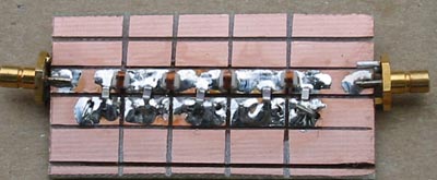 This is a photo of the completed filter. The above breadboard
has two wire vias for each capacitor ground. The capacitors are
size 0805, 5% C0G manufactured by AVX. I used SMB coaxial connectors
to facilitate measurement.
This is a photo of the completed filter. The above breadboard
has two wire vias for each capacitor ground. The capacitors are
size 0805, 5% C0G manufactured by AVX. I used SMB coaxial connectors
to facilitate measurement.
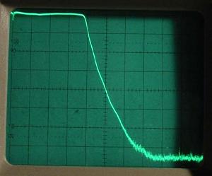 This photo shows the measured filter response. The gentle
passband loss in the simulation above is not evident, suggesting that the
inductor Q may be higher than the value of 20 used with the simulation.
The vertical divisions are 10 dB per division while the horizontal
is 20 MHz per division (total span of 200 MHz.)
This photo shows the measured filter response. The gentle
passband loss in the simulation above is not evident, suggesting that the
inductor Q may be higher than the value of 20 used with the simulation.
The vertical divisions are 10 dB per division while the horizontal
is 20 MHz per division (total span of 200 MHz.)
A wider 500 MHz total span showed two response peaks above 200 MHz,
both still more than 60 dB below the peak low pass response. Modeling
suggests that these come from series inductance in the chip capacitors
and mutual inductance in the form of long ground leads between the capacitors.